Welding is a common process for joining metals used a large variety of applications. A welding power supply is a device that provides and modulates an electric current to perform arc welding. A low-cost, entry-level welding machine is the so-calle...
Share
Welding is a common process for joining metals used a large variety of applications. A welding power supply is a device that provides and modulates an electric current to perform arc welding. A low-cost, entry-level welding machine is the so-called “buzz box” welder, as shown below, which is a simple power transformer with a saturable inductor or current-controlled circuit. The transformer’s two terminals are connected to base metal and stick electrode. When the stick electrode strikes the base metal, short circuit causes a larger current and ignites an arc, which melts the stick electrode and fills the gape of the base metal. Since the “buzz box” welders have limited control, the welding quality is largely depended on the welder’s operators. Heavy weight and noise are other drawbacks of the welders. With power semiconductor switches becoming available, advanced inverter welders were invented. By using high frequency switching technology and close-loop control, the welders become much lighter and easier to use. The block diagram of a low power inverter welder is shown below.

The torch and workpiece can be connected to the welder outputs in two different ways. When Torch is connected to the DC negative output, it is called “straight” welding (electron flows out from the torch), versa vise it is called “reverse” welding. Of which “reverse” welding is much more used today. It produces a good bead profile, deep penetration and overall better weld properties (bending, durability, porosity etc.) for bridges, ships, building’s metal construction. Then pipes and root passes on pipes. Generally, welding on higher strength and low alloy steels are exclusively done with DC “reverse” welding. DC “straight” welding is used on thin sheet metal in an attempt to prevent burning through the material or on places where metal would not be exposed to extreme temperature changes or hazardous water. Constant DC output welders are commonly used, but for Aluminum, alternating the output polarities in certain frequency and patterns ( AC welding) is required. This is because aluminum has basically two layers, the base aluminum and aluminum oxide. The oxide is essentially formed when metal is exposed to air and it has much higher melting point of about 3600-degree F. For example, base aluminum melts at 1200-degree F.The aluminum oxide must be cleaned off before the base metal starts to melt. If this is not performed the base metal can’t fuse properly. On thin sheets, base metal will overheat and liquefy before arc can get through the oxide. That’s where AC’s clean properties come in.
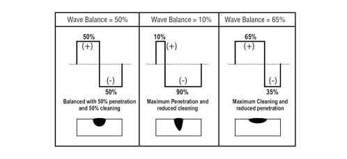
By controlling the DC output polarity and duration, high quality welding results can be achieved. The following is a WAVE BALANCE example used for Aluminum welding in AC HF TIG or AC LIFT TIG mode.

AC TIG Wave Balance
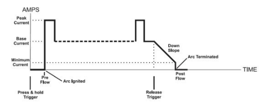
To be able to output positive DC, negative DC and AC outputs, the inverter welders need to add a polarity switch circuit at the outputs. Following is a universal high power welder circuit block diagram and current control profile.

SiC-Based Universal Inverter Welder Power Circuit Block Diagram

Inverter Welder Current Control Profile