صفحه اصلی / محصولات / اجزا / لامپ LED اسرام
| محل تولد: | آلمان |
| نام برند: | OSRAM |
| شماره مدل: | KW HJL531.TE |
| گواهینامه: | AEC-Q102 |
حداقل بسته بندی مقدار: | 2000 |
قیمت: | |
جزئیات بسته بندی: | تیپ و رول |
زمان تحویل: | |
شرایط پرداخت: |
OSLON® Black Flat S KW HJL531.TE OSLON Black Flat S میتواند به طیف گستردهای از نیازها پاسخ دهد. این دستگاه SMT بسیار پایدار و طولانیمدت است و میتواند با فرآیندهای استاندارد استفاده شود. طرح جدید پاد سوزنی میزان قابلیت اعتماد بالا و مدیریت حرارتی بهبود یافته را ارائه میدهد. چیپهای فشرده نه تنها خروجی نوری بالایی ارائه میدهند، بلکه قابل آدرسگذاری انفرادی هستند و تضاد بین چیپها تضمین شده است که این ویژگی این LED را به راهحل مناسبی برای پرتوی رانندگی تطبیقی (ADB) تبدیل میکند.
درخواست ها
- نور پیش رو ثابت
ویژگیها
- بستهبندی: بستهبندی Epoxy SMD
- فناوری چیپ: UX:3
- پراکنش نوری معمولی: 120 درجه (emiter لامبرتی)
- رنگ: Cx = 0.322, Cy = 0.334 طبق CIE 1931 (● سفید فوق العاده)
- کلاس مقاومت برابر زنگینی: 3B
- مجوزها: با مجوز AEC-Q102 و سطح RV-سطح 1
- ESD: 8 kV بر اساس ANSI/ESDA/JEDEC JS-001 (HBM, کلاس 3B)
اطلاعات سفارش

بیشترین رتبهبندیها

* عمر میانی (L70/B50) برای Tj = 175°C، 100h است.
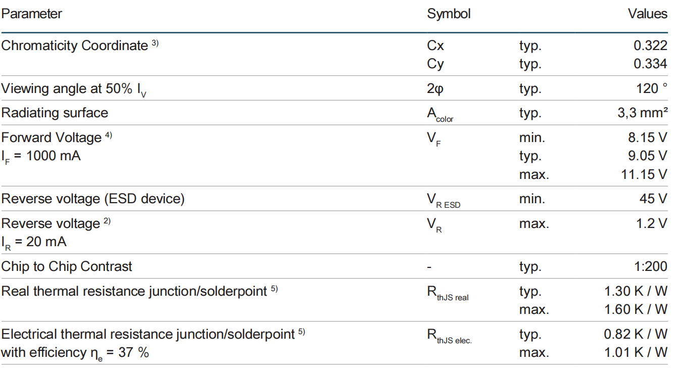
ویژگیها
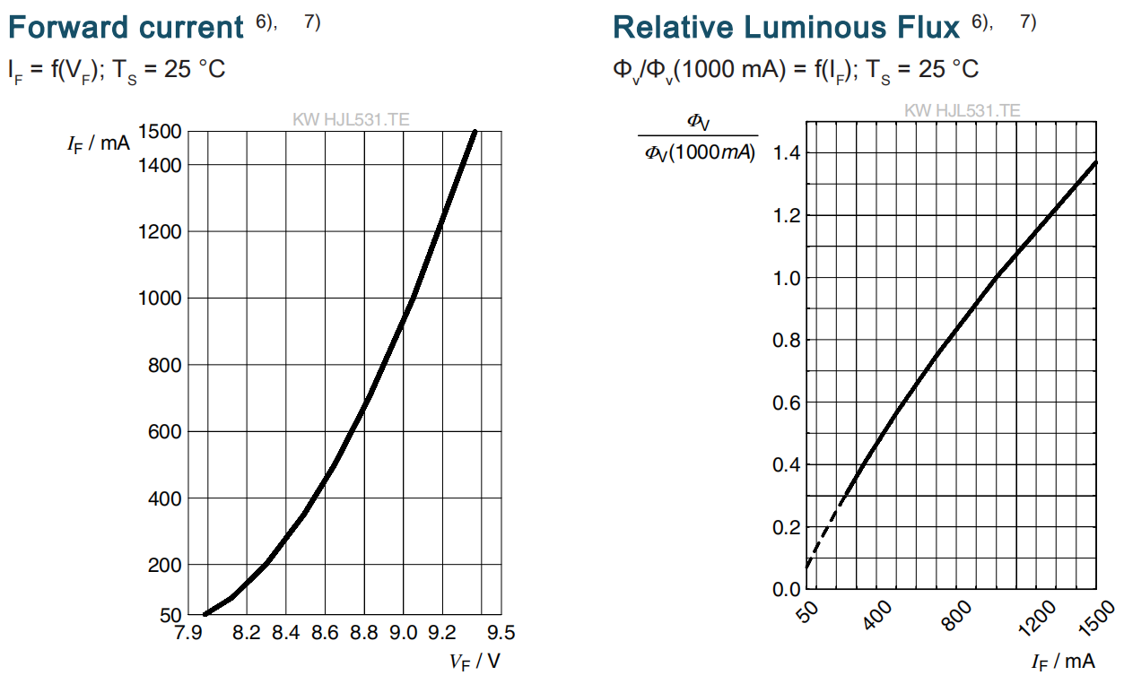
I F = 1000 mA; TS = 25 °C
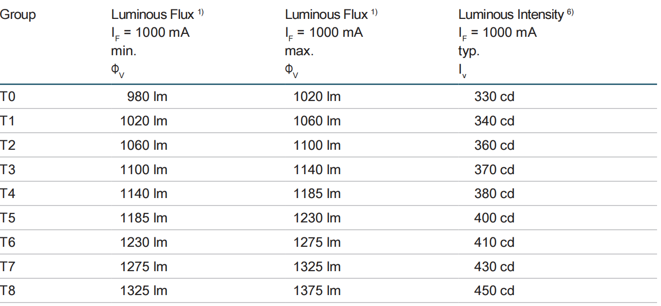
گروههای درخشندگی
گروههای ولتاژ جلویی

گروههای مختصات کروماسیته ۳)
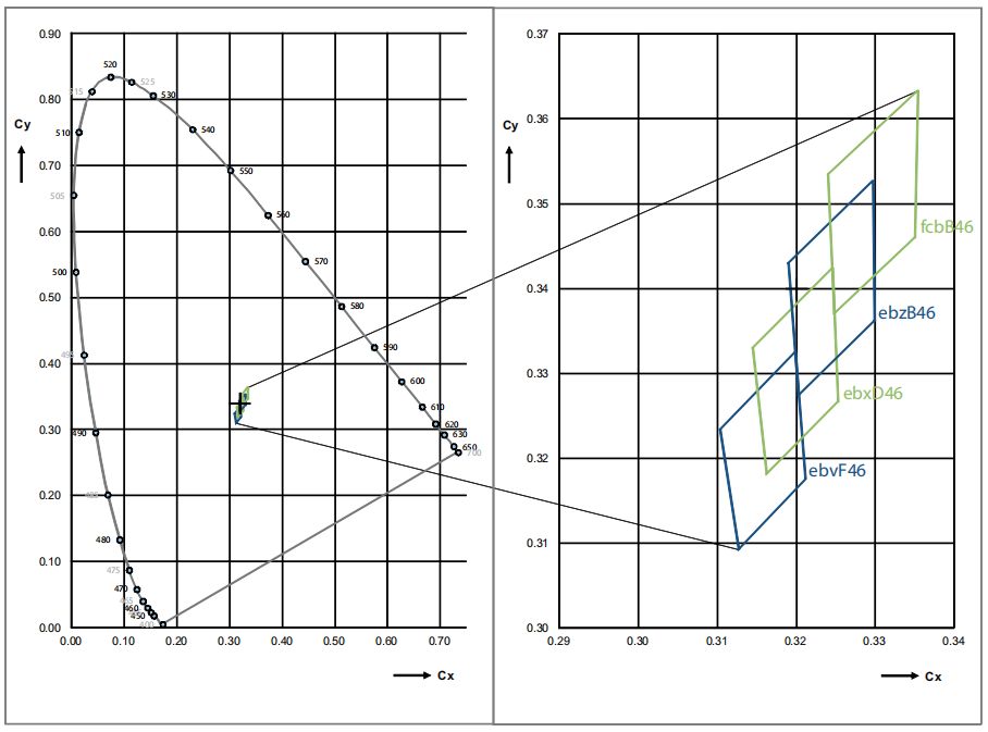
گروههای مختصات کروماسیته ۳)
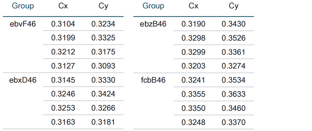
نام گروه روی برچسب
مثال: T0-ebvF46-DF

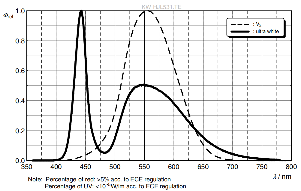
emitانسیت طیفی نسبی 6)
Φrel = f (λ); IF = 1000 mA; TS = 25 °C
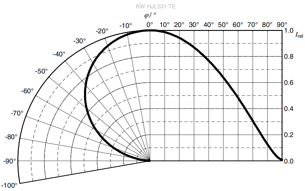
ویژگیهای پرتو زنی 6)
I rel = f (ϕ); TS = 25 °C

نمودار ابعاد 8)
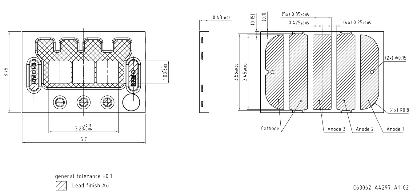
اطلاعات بیشتر:
وزن تقریبی: 35.0 میلی گرم
آزمون خوردگی: کلاس: 3B
شرایط آزمایش: 40°C / 90 % RH / 15 ppm H2S / 14 روز (سختتر از IEC
60068-2-43)
نکته ESD: دستگاه توسط دستگاه ESD محافظت میشود که به صورت موازی با چیپ متصل شده است.
مدار الکتریکی داخلی

پد جوشکاری پیشنهادی 8)
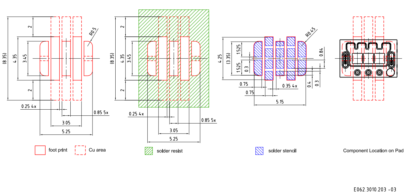
برای نتایج بهتر در اتصال جوش، توصیه میکنیم تحت جو استاندارد نیتروژن جوش کنید. بستهبندی برای تمیز کردن فوق صوت مناسب نیست. برای تضمین قابلیت اعتماد بالا در اتصال جوش و کاهش خطر شکست اتصالات جوش، مشتری مسوول ارزیابی ترکیب ماده فلزی PCB و مواد جوش برای کاربرد خود است.
نمودار جوشکاری بازگشتی
محصول مطابق با سطح MSL 2 طبق استاندارد JEDEC J-STD-020E است.
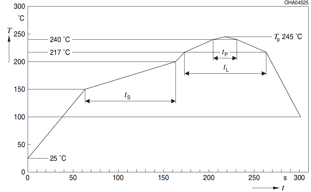
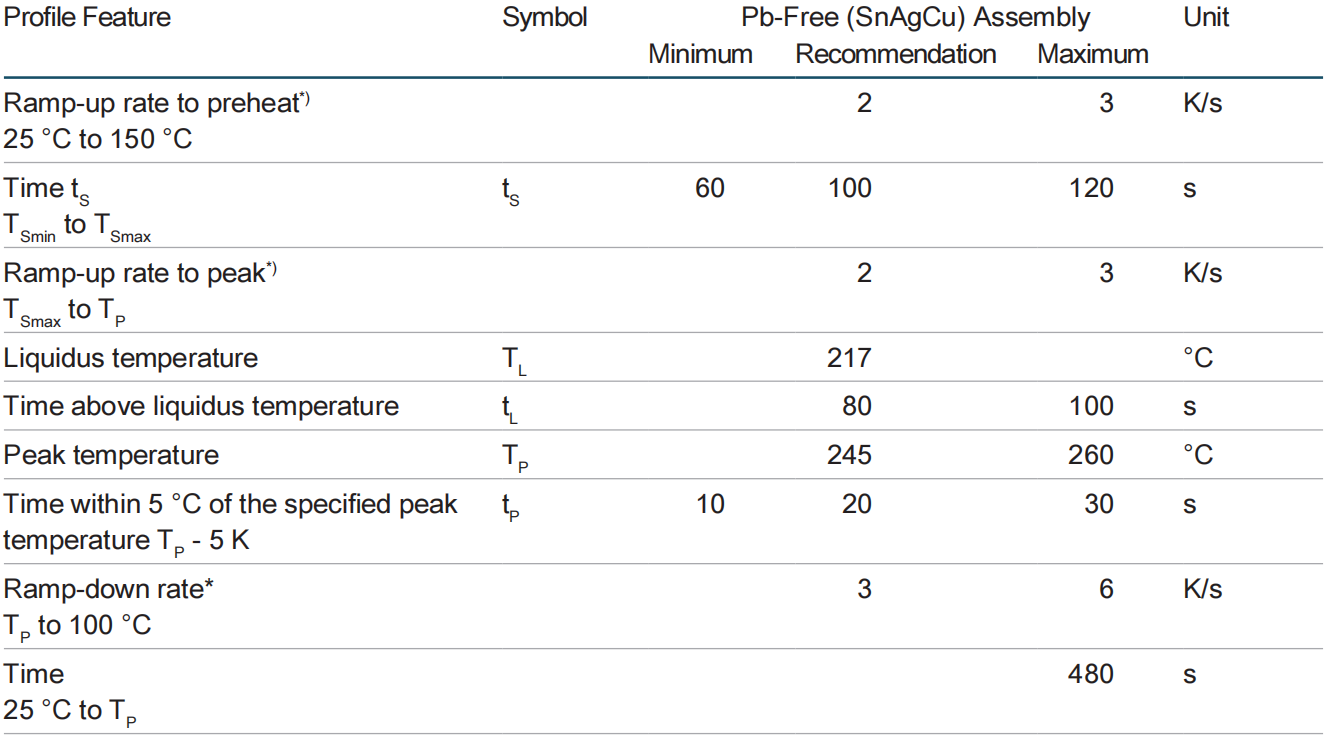
تمام دمایها به مرکز بسته اشاره دارد، که از بالای مولفه اندازهگیری شده است
* محاسبه شیب DT/Dt: حداکثر Dt 5 ثانیه؛ رعایت برای کل محدوده T
چسباندن 8)
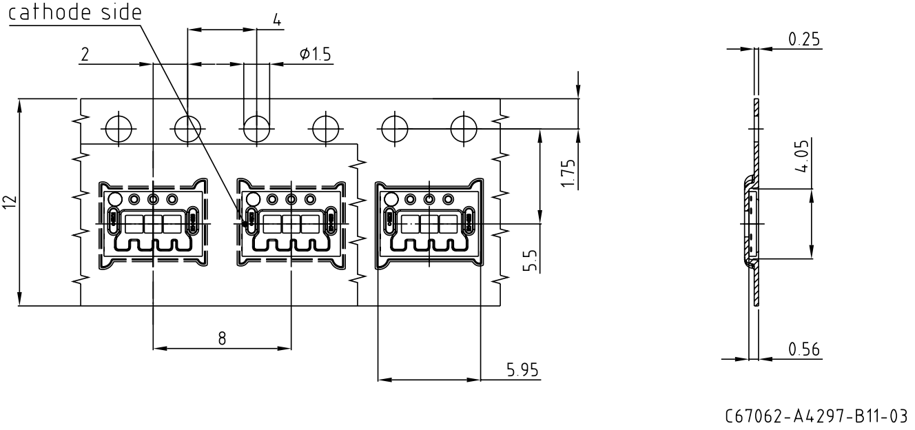
تیپ و رول 9)
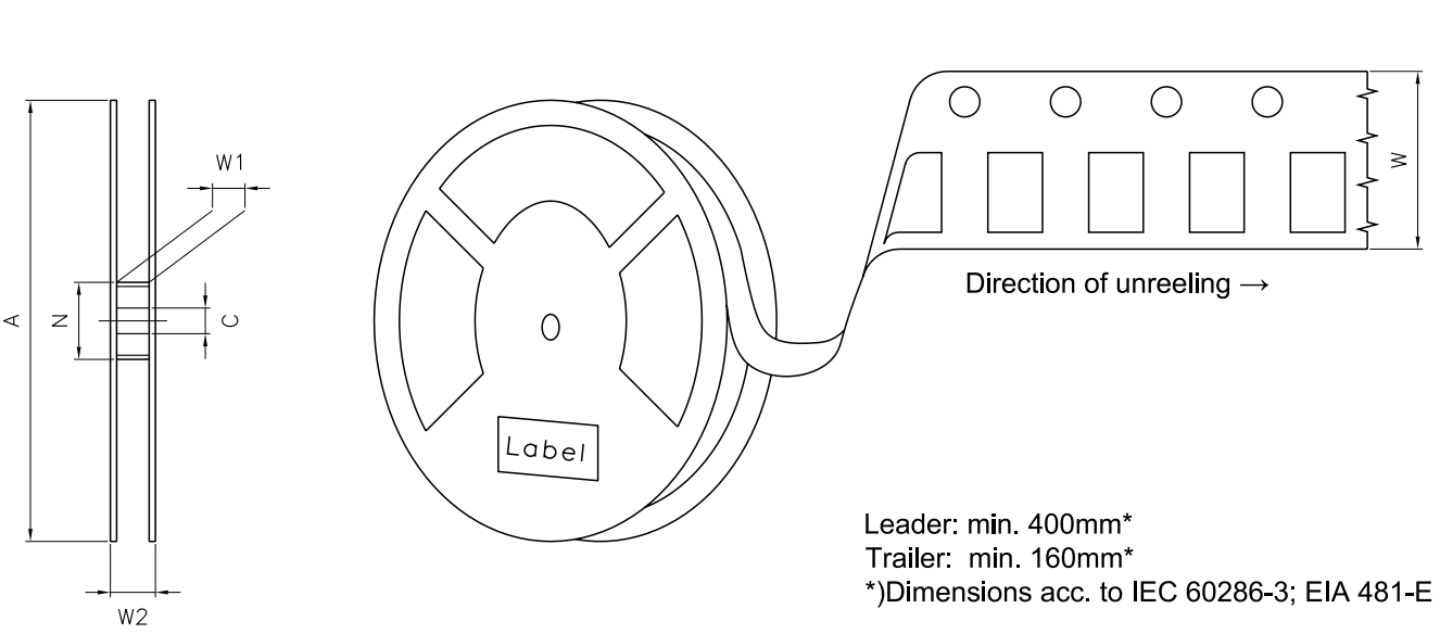
ابعاد توری

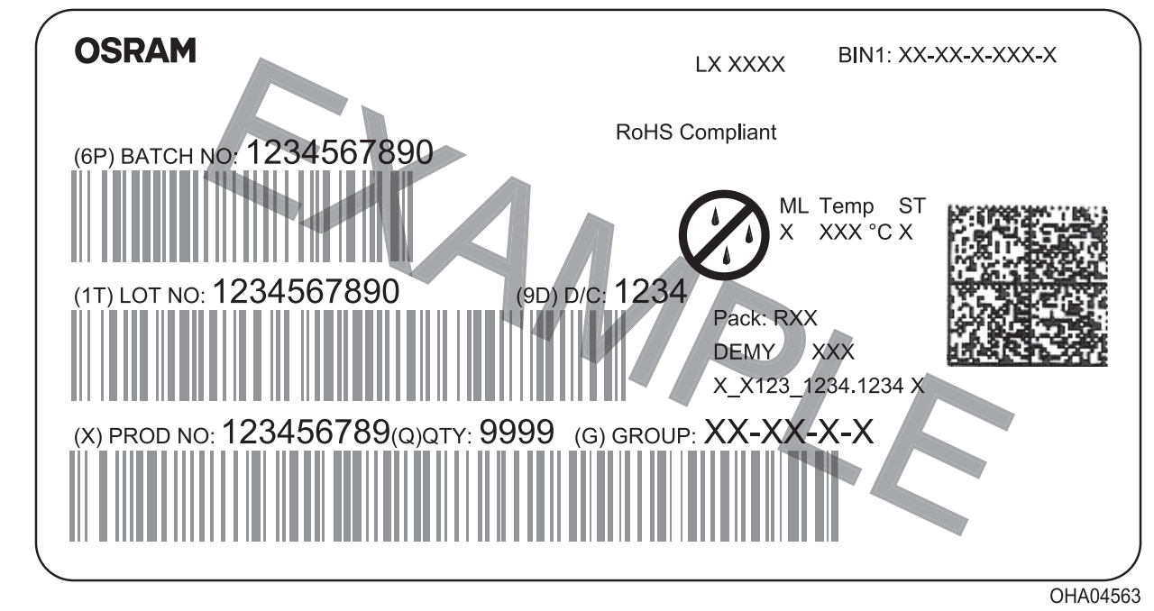
برچسب بارکد-محصول (BPL)
فرآیند و مواد بستهبندی خشک 8)
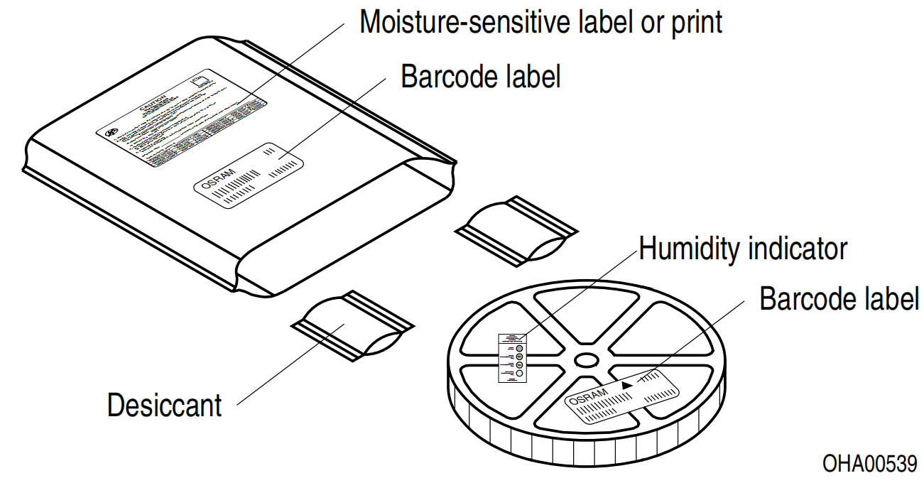
محصول حساس به رطوبت در یک کیسه خشک بستهبندی میشود که شامل جذبکننده رطوبت و کارت رطوبتی طبق استاندارد JEDEC-STD-033 است.
سیستم نامگذاری نوع
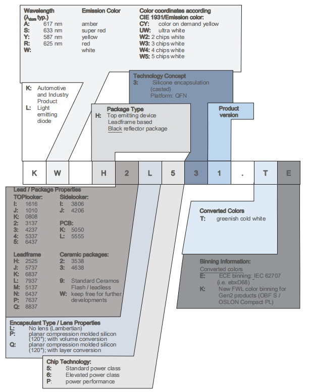
یادداشتها
ارزیابی ایمنی چشم بر اساس استاندارد IEC 62471:2006 (ایمنی فتو-بیولوژیک لامپها و سیستمهای لامپ) انجام میشود. درون سیستم گروهبندی ریسک این استاندارد IEC، دستگاه مشخص شده در این فهرست مشخصات به دسته ریسک متوسط (زمان نور خوردن 0.25 ثانیه) تعلق دارد. تحت شرایط واقعی (برای زمان نور خوردن، شرایط بینی پupilها، فاصله مشاهده)، فرض بر این است که هیچ تهدیدی به چشم از این دستگاهها وجود ندارد. با این حال، باید ذکر شود که منابع نوری شدید به علت اثر غیرمستقیم قوی خود، بالا نور دارند. وقتی به منابع نوری قوی نگاه میکنیم (مثل چراغهای جلوی ماشین)، کاهش موقت توانایی دید و تصاویر باقیمانده ممکن است رخ دهد که با توجه به شرایط، منجر به اضطراب، ناراحتی، کاهش دید و حتی تصادفات میشود.
زیربخشهای این دستگاه، علاوه بر مواد دیگر، شامل مصالح پر شده فلزی شامل نقره است. مصالح پر شده فلزی ممکن است توسط محیطهای حاوی اثرات عدوانی تحت تأثیر قرار گیرند. بنابراین، توصیه میکنیم که مشتریان معرض قرار گرفتن دستگاه به این مواد عدوانی را طی ذخیره سازی، تولید و استفاده به حداقل برسانند. دستگاههایی که در آزمایشهای انجام شده بالا رنگآمیزی قابل مشاهدهای نشان دادند، انحراف عملکردی در حدود خطای تعیین شده طی مدت زمان آزمایش نشان ندادند. حدود خطاها در IEC60810 توضیح داده شده است.
برای اطلاعات بیشتر مرتبط با کاربرد، مراجعه کنید به https://ams-osram.com/support/application-notes
اعلام عدم مسئولیت
توجه!
اطلاعات، نوع مولفه را توصیف میکند و نباید به عنوان ویژگیهای مطمئن در نظر گرفته شود. شرایط تحویل و حق تغییر در طراحی محفوظ است. به دلیل نیازهای فنی، مولفهها ممکن است شامل مواد خطرناک باشند.
برای اطلاعات مربوط به انواع مورد سؤال، با سازمان فروش ما تماس بگیرید.
اگر چاپ شده یا دانلود شده باشد، لطفاً آخرین نسخه را در سایت ما پیدا کنید.
بسته بندی
لطفاً از عملیات بازیافتی که برای شما شناخته شده است استفاده کنید. ما نیز میتوانیم به شما کمک کنیم - با اداره فروش نزدیک به شما تماس بگیرید. با توافق، مواد بستهبندی را اگر مرتب شده باشد، باز خواهیم گرفت. شما باید هزینههای حمل و نقل را بپردازید. برای مواد بستهبندی که به ما بدون مرتبسازی بازگردانده میشوند یا که ما موظف به قبول آن نیستیم، باید هزینههای تحمیلی را صورتحساب کنیم.
دستگاهها و اجزای ایمنی تابعی یا برنامههای مرتبط یا دستگاههای پزشکی و برنامههای مرتبط
اجزای ما برای استفاده به عنوان مؤلفه ایمنی مربوط یا برای استفاده در دستگاههای پزشکی طراحی، ساخت یا آزمایش نشدهاند.
محصولات ما در سطح ماژول و سیستم برای این کاربرد معتبر نیستند.
در صورتی که خریدار یا مشتری تأمین شده توسط خریدار، قصد داشته باشند مولفههای ما را در دستگاههای ایمنی محصولات یا دستگاههای پزشکی استفاده کنند، خریدار و/یا مشتری باید همکار فروش محلی ما را به طور فوری مطلع کند و ما و خریدار و/یا مشتری، درخواست خاص مشتری را بین ما و خریدار و/یا مشتری تحلیل و هماهنگ خواهیم کرد.
فرهنگ لغت
1) روشنایی: مقادیر روشنایی در حین یک نبض جریان به مدت معمولاً 25 میلی ثانیه اندازهگیری میشوند، با تکرارپذیری داخلی ±8٪ و عدم قطعیت گسترش یافته ±11٪ (طبق GUM با عامل پوشش k = 3).
2) عملکرد معکوس: این محصول قصد دارد با اعمال جریان جلو در دامنه مشخص شده عمل کند. اعمال هر بایاس معکوس مداوم یا بایاس جلو زیر دامنه ولتاژ تابش نوری باید جلوگیری شود، زیرا ممکن است مهاجرتی ایجاد کند که ویژگیهای الکترو-نوری را تغییر دهد یا LED را آسیب برساند.
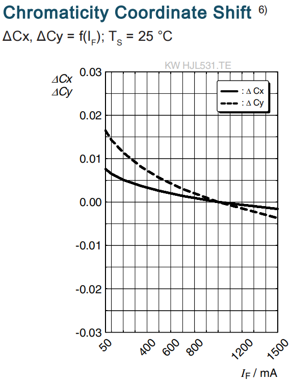
۳) گروههای مختصات کروماسیتی: مختصات رنگی در طول یک پالس جریان معمولاً ۲۵ میلی ثانیه اندازهگیری میشوند، با تکرارپذیری داخلی ±۰.۰۰۵ و عدم قطعیت گسترشیافته ±۰.۰۱ (طبق GUM با عامل پوشش k = 3).
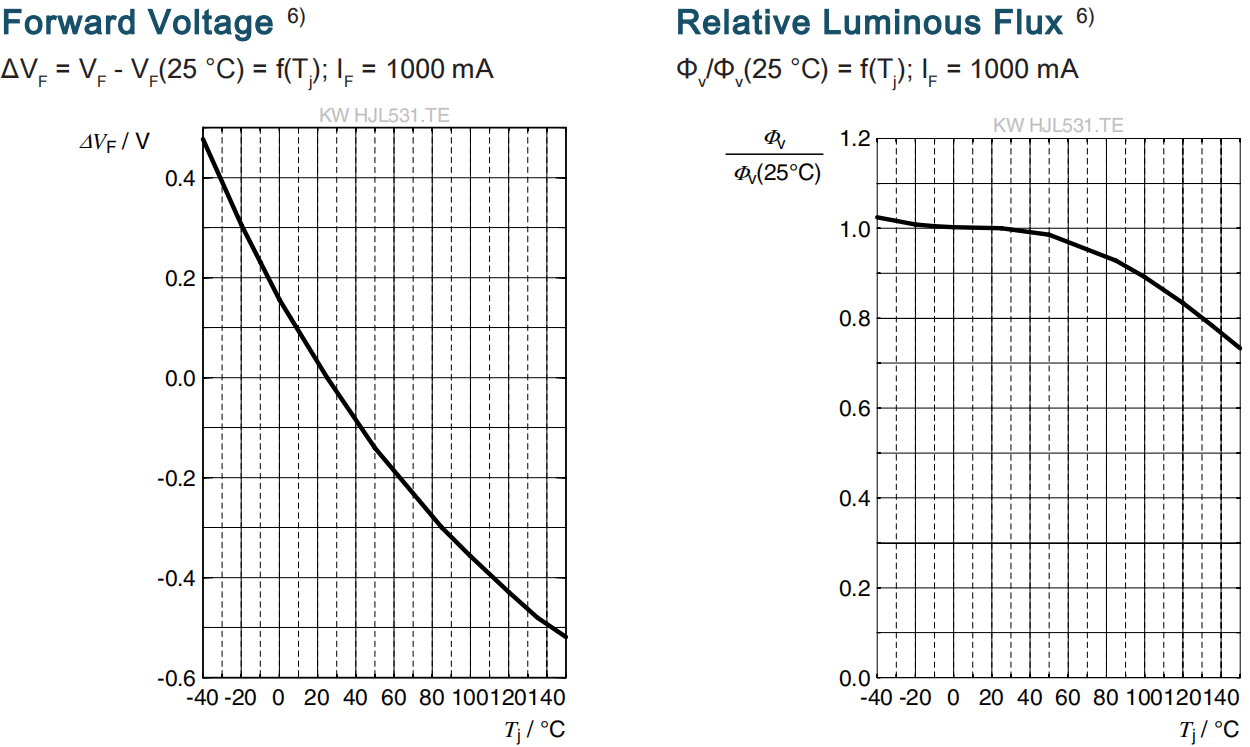
4) ولتاژ جلوگام: ولتاژ جلوگام در طول یک پالس جریان معمولاً ۸ میلی ثانیه اندازهگیری میشود، با تکرارپذیری داخلی ±۰.۰۵ ولت و عدم قطعیت گسترشیافته ±۰.۱ ولت (طبق GUM با عامل پوشش k = 3).
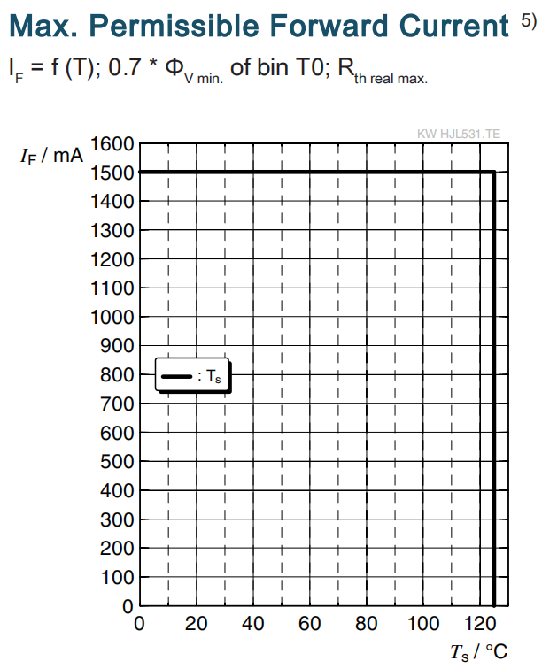
5) مقاومت حرارتی: Rth max بر اساس مقادیر آماری (6σ) است که برای کاهش عملکرد استفاده میشود.
۶) ارزشهای معمول: به دلیل شرایط ویژه فرآیندهای تولید دستگاههای نیمهرسانا، دادههای معمول یا همبستگیهای محاسبهشده پارامترهای فنی فقط اعداد آماری را نشان میدهند. این اعداد لزوماً با پارامترهای واقعی هر محصول تکی مطابقت ندارد که ممکن است از دادههای معمول و همبستگیهای محاسبهشده یا خط مشخصه معمول متفاوت باشد. اگر درخواست شود، مثلاً به خاطر بهبودهای فنی، این دادههای معمول بدون اطلاع قبلی تغییر خواهد کرد.
7) خط مشخصه: در بازهای که خط نمودار قطع شده است، باید اختلافات بیشتری بین دستگاههای تکی درون یک واحد بستهبندی منتظر شوید.
8) حاشیه اندازهگیری: هرگز تا زمانی که در نقشه ذکر نشده باشد، حاشیهها با ±0.1 مشخص شدهاند و ابعاد به میلیمتر مشخص شدهاند.
9) نوار و بوبین: همه ابعاد و حاشیهها بر اساس IEC 60286-3 مشخص شده و به میلیمتر است.
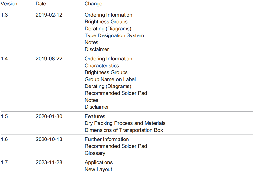
تاریخچه نسخه
