ホームペーじ / 製品 / コンポーネント / SiC MOSFET
| 原産地: | 浙江 |
| ブランド名: | Inventchip Technology |
| 型番: | IV2Q12030D7Z |
| 認証: | AEC-Q101認証取得 |
特徴
第2世代SiC MOSFET技術+18Vゲートドライブ
高いブロック電圧と低いオン抵抗
低容量による高速スイッチング
高い接合温度動作能力
非常に高速で堅牢なインヒンティブダイオード
ドライバ回路設計を容易にするケルビングエート入力
申請
自動車運転手
太陽光インバーター
自動車用 DC/DC コンバーター
自動車用コンプレッサーインバーター
スイッチング電源
概要:
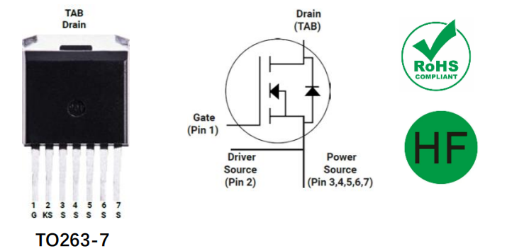
マーク付き図:

絶対最大格付け (TC=25°C でない場合を除く)
| シンボル | パラメータ | 価値 | ユニット | 試験条件 | 注記 |
| VDS | ドレイン-ソース間電圧 | 1200 | v | VGS =0V, ID =100μA | |
| VGSmax (DC) | 最大DC電圧 | -5 から 20 | v | 静的 (DC) | |
| VGSmax (スパイク) | 最大スパイク電圧 | -10 から 23 | v | 動作サイクル<1%、パルス幅<200ns | |
| VGSon | 推奨されるオン電圧 | 18±0.5 | v | ||
| VGSoff | 推奨されるオフ電圧 | -3.5 から -2 | v | ||
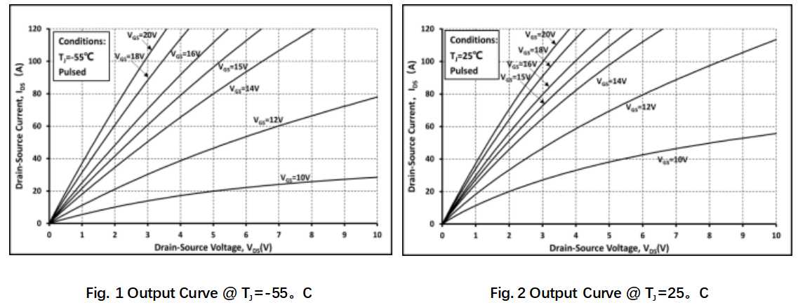
| id | ドレイン電流(連続) | 79 | A について | VGS =18V、TC =25°C | 図23 |
| 58 | A について | VGS =18V, TC =100°C | |||
| IDM | ドレイン電流(パルス) | 198 | A について | SOAによってパルス幅が制限される | 図26 |
| Ptot | 総電力損失 | 395 | W について | TC =25°C | 図24 |
| ターゲット・ストーブ | 保管温度範囲 | -55から175 | °C | ||
| Tj | 動作時の接合温度 | -55から175 | °C | ||
| 翻訳 | はんだ付け温度 | 260 | °C | リード部でのみ波動はんだ付けを許可、本体から1.6mm離して10秒間 |
熱データ
| シンボル | パラメータ | 価値 | ユニット | 注記 |
| Rθ(J-C) | 接合部からケースまでの熱抵抗 | 0.38 | °C/W | 図23 |
電気的特性 (TC =25℃、特に指定がない場合)
| シンボル | パラメータ | 価値 | ユニット | 試験条件 | 注記 | ||
| 分。 | タイプする | マックス。 | |||||
| IDSS | ゼロゲート電圧ドレイン電流 | 5 | 100 | 微分数 | VDS =1200V, VGS =0V | ||
| IGSS | ゲート漏れ電流 | ±100 | NA | VDS =0V, VGS = -5~20V | |||
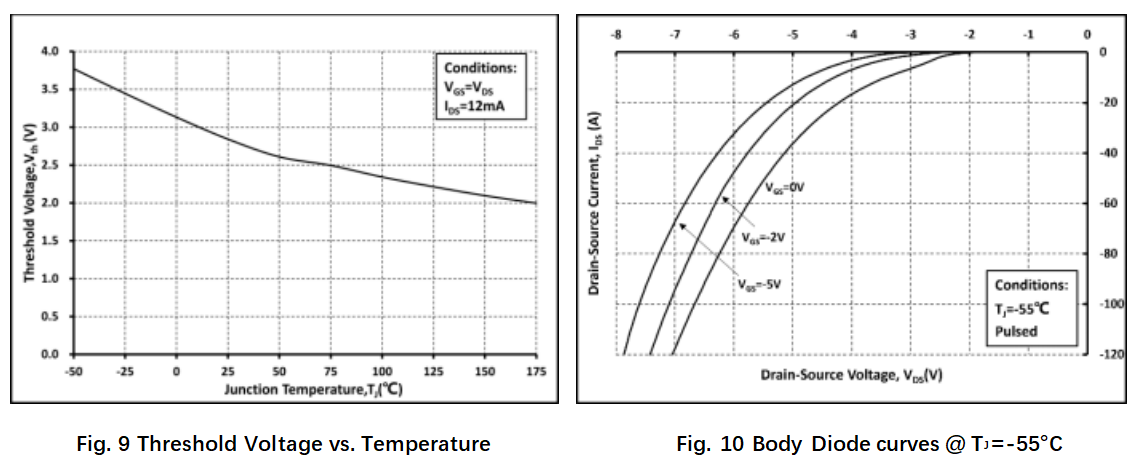
| VTH | ゲート 限界電圧 | 1.8 | 2.8 | 4.5 | v | VGS=VDS , ID =12mA | 図8、9 |
| 2.0 | VGS=VDS , ID =12mA @ TJ =175℃ | ||||||
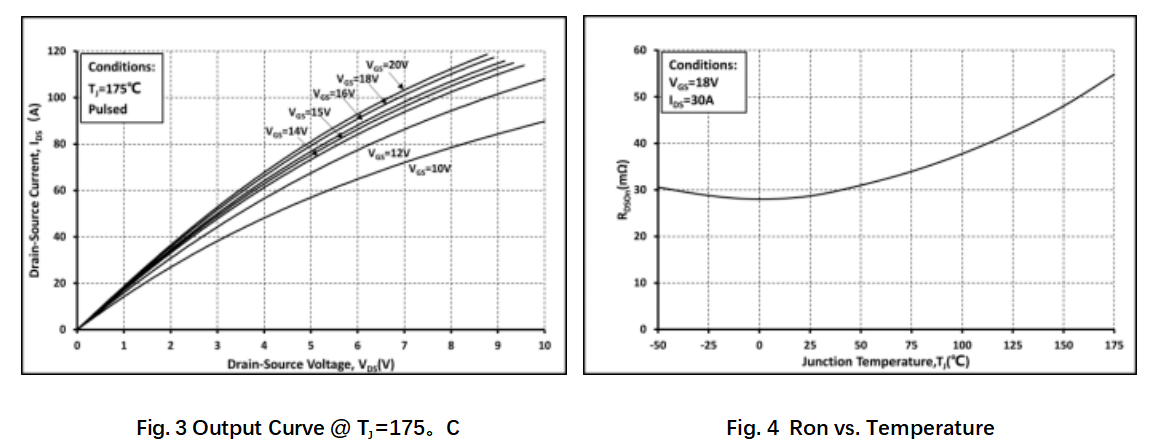
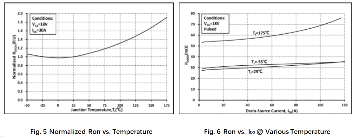
| ロン | 静的なドレイン・ソース間オン抵抗 | 30 | 39 | mΩ | VGS =18V、ID =30A @TJ =25℃ | 図4、5、6、7 | |
| 55 | mΩ | VGS =18V、ID =30A @TJ =175℃ | |||||
| 36 | 47 | mΩ | VGS =15V、ID =30A @TJ =25℃ | ||||
| 58 | mΩ | VGS =15V、ID =30A @TJ =175℃ | |||||
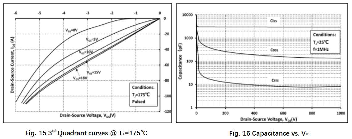
| Ciss | 入力容量 | 3000 | PF | VDS=800V、VGS =0V、f=1MHz、VAC=25mV | 図16 | ||
| Coss | 輸出容量 | 140 | PF | ||||
| Crss | 逆転移容量 | 7.7 | PF | ||||
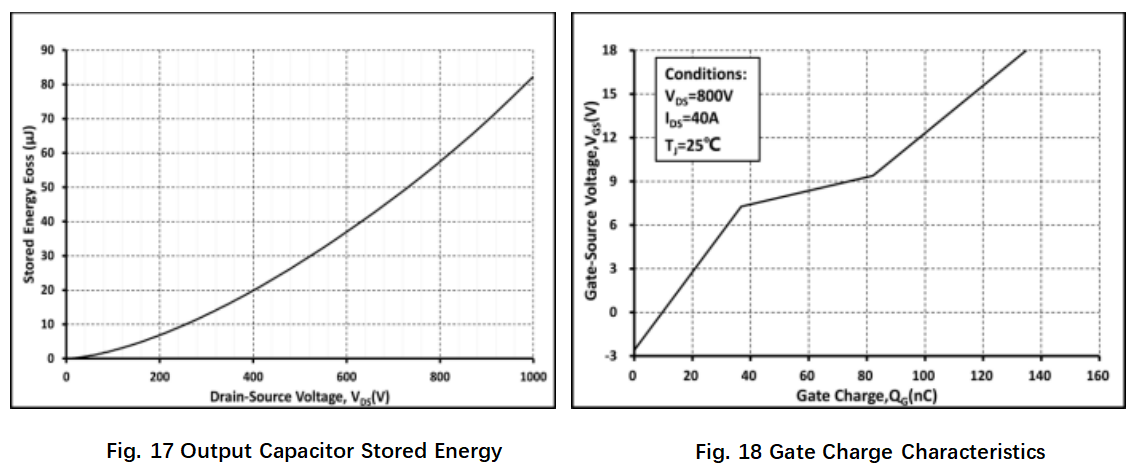
| Eoss | Cossに蓄えられたエネルギー | 57 | μJ | 図17 | |||
| 司令部 | 総ゲート電荷 | 135 | nC | VDS =800V、ID =40A、VGS =-3から18V | 図18 | ||
| Qgs | ゲート-ソース充電量 | 36.8 | nC | ||||
| Qgd | ゲート-ドレイン充電量 | 45.3 | nC | ||||
| Rg | ゲート入力抵抗 | 2.3 | Ω | f=1MHz | |||
| エオン | オンスイッチングエネルギー | 856.6 | μJ | VDS =800V、ID =40A、VGS =-3.5から18V、RG(外部) =3.3Ω、L=200μH、TJ =25℃ | 図19、20 | ||
| オーフ | オフスイッチングエネルギー | 118.0 | μJ | ||||
| オン (オン) | オンする遅延時間 | 15.4 | NS | ||||
| について | 昇る時間 | 24.6 | |||||
| 消して | オフ遅延時間 | 28.6 | |||||
| TF | 秋の時間 | 13.6 | |||||
逆ダイオード特性 (TC =25℃、特に指定がない場合)
| シンボル | パラメータ | 価値 | ユニット | 試験条件 | 注記 | ||
| 分。 | タイプする | マックス。 | |||||
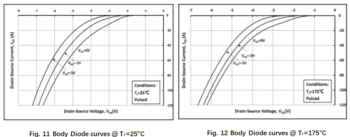
| VSD | ダイオード前向き電圧 | 4.2 | v | ISD =30A, VGS =0V | 図10、11、12 | ||
| 4.0 | v | ISD =30A, VGS =0V, TJ =175℃ | |||||
| trr | 逆回復時間 | 54.8 | NS | VGS=-3.5V/+18V, ISD =40A, VR =800V, RG(ext) =13Ω L=200μH di/dt=3000A/μs | |||
| Qrr | 逆回復電荷 | 470.7 | nC | ||||
| IRRM | ピーク逆回復電流 | 20.3 | A について | ||||
典型的性能(カーブ)
