Főoldal / Termékek / Komponensek / SiC SBD
| Származási hely: | Zhejiang |
| Márkaneve: | Inventchip Technology |
| Modell száma: | IV1D12040U3Z |
| Tanúsítvány: | AEC-Q101 minősítve |
| Minimális csomagolási mennyiség: | 450db |
| Ár: | |
| A csomagolás részletei: | |
| Szállítási idő: | |
| Kifizetési feltételek: | |
| Szállítási kapacitás: |
Jellemzők
Maximális csatlakozási hőmérséklet 175°C
Magas túlzó áramkapacitás
Nulla visszafelé haladó áram
Nulla előre irányuló visszaáramlás feszültség
Magasfrekvenciás működés
Hőfüggetlen kapcsolási viselkedés
Pozitív hőmérsékleti együttható az VF-n
AEC-Q101 minősítve
A kérelmek
Autósi Inverter Ellenforgási Diodák
EV töltőállományok
Bécs 3-fázisú PFC
Napenergia Teljesítmény Növelés
Váltóáramos Tápegységek
Az ábrázolás
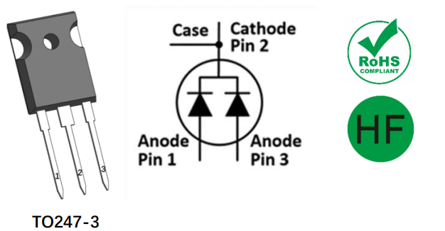
Jelölési diagram

Abszolút maximális minősítés (TC=25°C külön megjelölés nélkül)
| Szimbólum | Paraméter | érték | egység |
| VRRM | Fordított feszültség (ismétlődő csúcs) | 1200 | V. |
| VDC | DC blokkoló feszültség | 1200 | V. |
| Ha | Előrébocsájtott áram (folyamatos) @Tc=25°C | 54* | A |
| Előrébocsájtott áram (folyamatos) @Tc=135°C | 28* | A | |
| Előrébocsájtott áram (folyamatos) @Tc=151°C | 20* | A | |
| IFSM | Szökéses nem ismétlődő előrébbi áram szinusz félhullám @Tc=25°C tp=10ms | 140* | A |
| A FVK | Szökéses ismétlődő előrébbi áram (Gy=0,1Hz, 100ciklus) szinusz félhullám @Tamb =25°C tp=10ms | 115* | A |
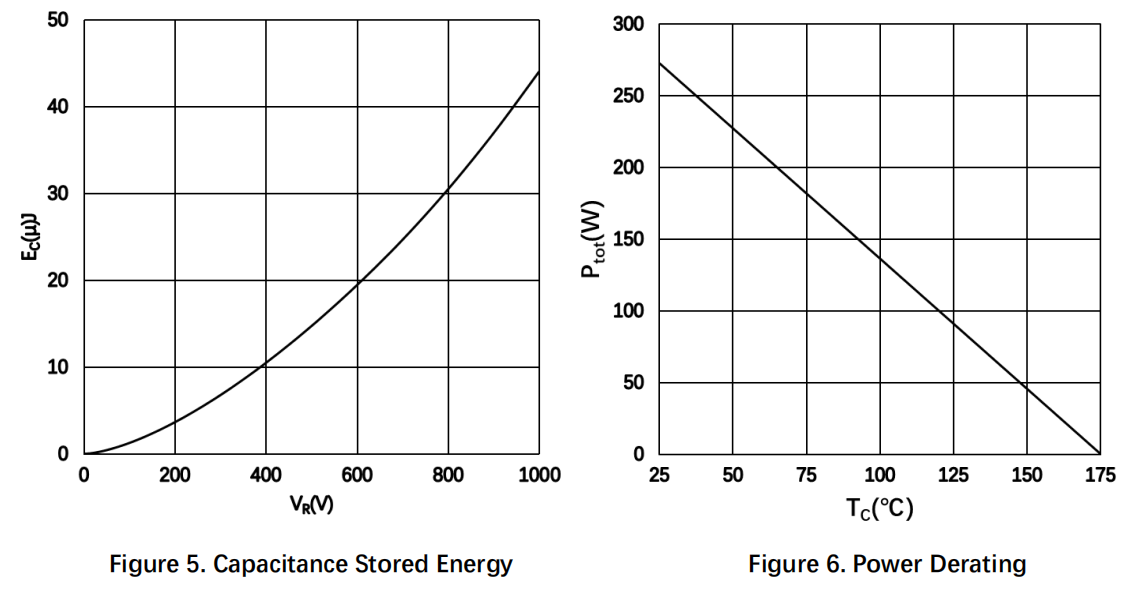
| Ptot | Teljes hőfelszívás @ Tc=25°C | 272* | W |
| Teljes hőfelszívás @ Tc=150°C | 45* | ||
| I2t érték @Tc=25°C tp=10ms | 98* | A2s | |
| TSTG | Tárolóhőmérséklet-tartomány | -55 to 175 | °C |
| Tj | Működési csatolási hőmérsékleti tartomány | -55 to 175 | °C |
*Per Leg
Az Maximum Ratings táblázatban felsorolt értékeket túlmenő tényezők károsíthatják a berendezést. Ha bármely korlát meghaladva van, nem lehet feltételezni a berendezés funkcióit, károsodás történhet és a megbízhatóság befolyásolható.
A funkciókat nem lehet feltételezni, károsodás történhet és a megbízhatóság befolyásolható.
Elektromos jellemzők
| Szimbólum | Paraméter | - Tipikus. | - Max, kérlek! | egység | A vizsgálati feltételek | Megjegyzés |
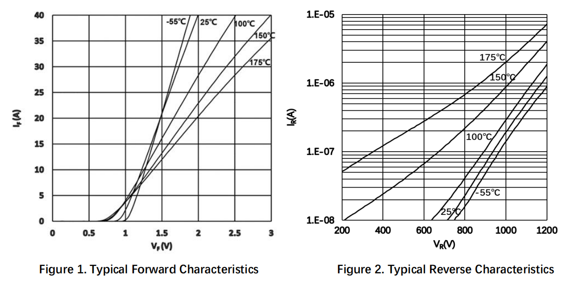
| VF | Előre Feszültség | 1.48* | 1.8* | V. | IF = 20 A TJ =25°C | Ábr. 1 |
| 2.1* | 3.0* | HA = 20 A TJ =175°C | ||||
| Ir | Fordított áram | 10* | 200* | μA | VR = 1200 V TJ =25°C | Ábr. 2 |
| 45* | 800* | VR = 1200 V TJ =175°C | ||||
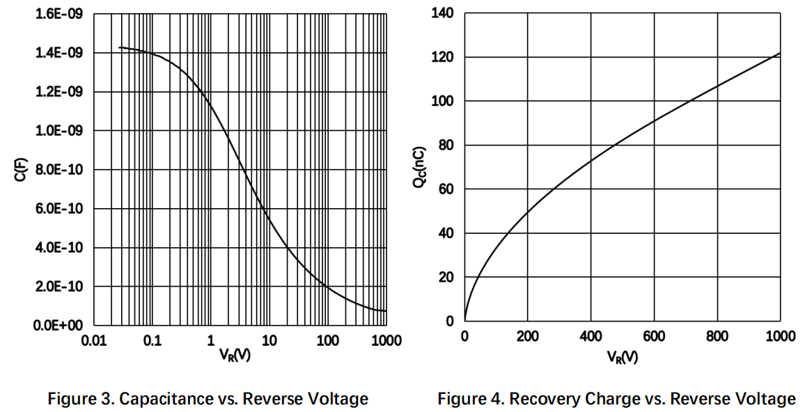
| C | Teljes kapacitás | 1114* | PF | VR = 1 V, TJ = 25°C, f = 1 MHz | Ábra 3 | |
| 100* | VR = 400 V, TJ = 25˚C, f = 1 MHz | |||||
| 77* | VR = 800 V, TJ = 25˚C, f = 1 MHz | |||||
| QC | Teljes kapacitív töltés | 107* | NC | VR = 800 V, TJ = 25°C, Qc = C(v)dv | Ábra 4 | |
| ec | Tárolt kapacitás-energia | 31* | μJ | VR = 800 V, TJ = 25°C, Ec = C(v) ⋅vdv | Ábra 5 |
*Per Leg
Hőmérsékleti jellemzők (per láb)
| Szimbólum | Paraméter | - Tipikus. | egység | Megjegyzés |
| Rth(j-c) | Hőellenállás a csatolástól a fedélzéhez | 0.55 | °C/W | Ábra 7 |
Tipikus teljesítmény (per láb)
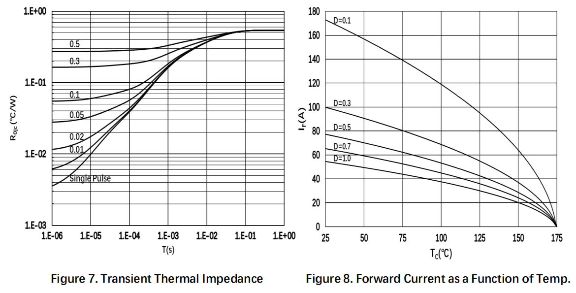
Csomag méretei
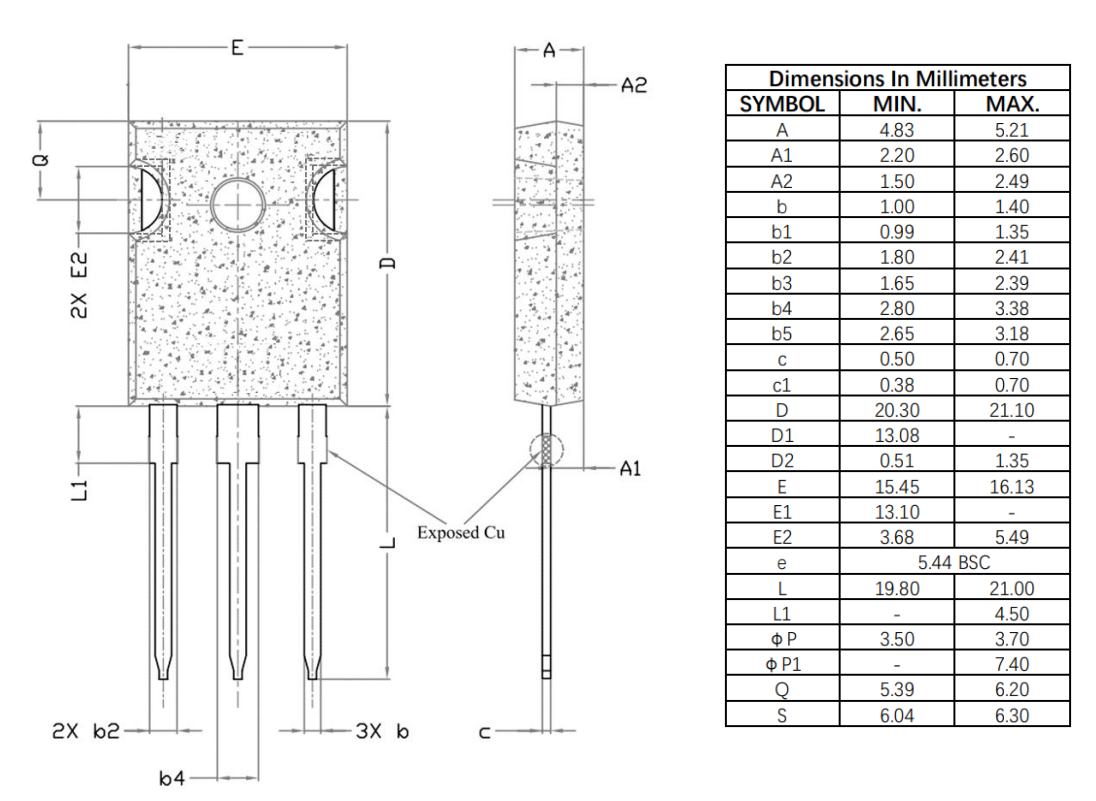
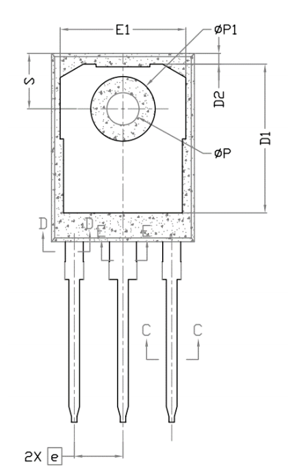
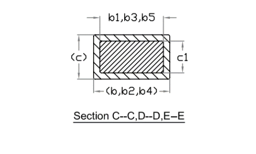
Megjegyzés:
1. Csomag referencia: JEDEC TO247, AD változat
2. Minden méret milliméterben van megadva
3. Szókszereltés szükséges, a nyílás kerekített vagy téglalap alakú lehet
4. A méreteket és súlyt a forma flash nélkül kell megadni
5. Változhat without értesítés nélkül